User benefits
Everybody involved in computer-aided engineering (CAE) has to deal with numerous designs that vary in geometry, material, and boundary conditions. ModelCompare is a quick-look tool capable of determining the differences between two FE models that are discretized similarly. With ModelCompare, you can quickly compare two FE models within the used visualization tool without going through the burden of manually determining the differences. A report can be generated to document the changes.
Our contribution
At Fraunhofer SCAI, we thrive at the crossroads of mathematics and data analysis. This enables us to provide cutting-edge tools that address the everyday needs of CAE engineers. They often need to compare and identify parts from different models when they analyze different simulation results. Therefore, we developed this tool as one step of an overall simulation data analysis workflow.
A seamless interface as a plug-in
ModelCompare is available as a plug-in for GNS Animator and BETA CAE Systems META*. It can also be provided as a seamless, versatile interface for the visualization tool of your choice or as a stand-alone tool.
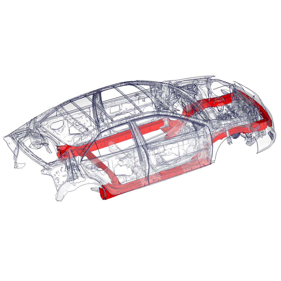
Geometry and mesh changes
Accurate estimation and depiction of the differences in the geometry of two FE models are made based on their nodal positions. Additionally, parts with the same shape but different mesh configurations are detected and displayed.
Duplicated parts in one model
Parts with the same shape and mesh, which occur several times in a model, are identified independently of their orientation.
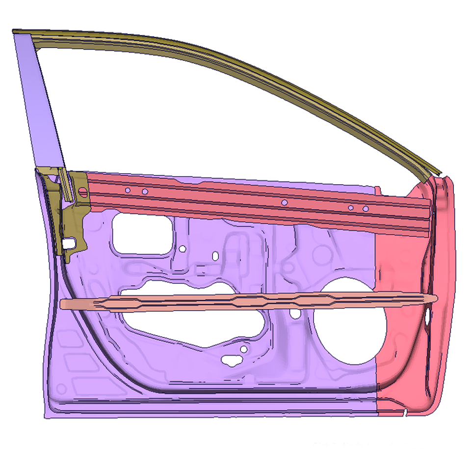
Multi-parts detection
ModelCompare identifies a part in the first model that is split into multiple parts in the second model, and treats it as a set consisting of these parts.
New and missing parts / elements
New parts that have been added to or parts that have been removed from the model are detected and visualized. Elements missing in a part in one model, e.g., due to improper meshing, are also detected. The tool also detects if an element belongs to two different parts in the two models.
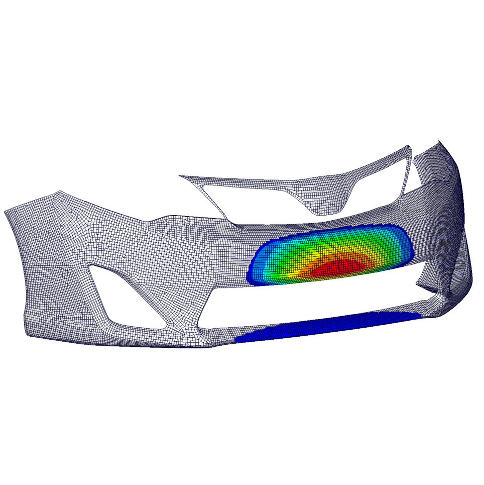
Mass, material-ID, thickness, or function changes
Differences in mass, material-ID, thickness, or user-specified function values between both models are detected. Here, thickness changes can be part-based or element-based, while function values can come from nodes or elements.
Detection of changes in spotweld, RBEs, and adhesives
Differences in the attributes of spot welds (e.g., part identifiers, element identifiers, connected parts) are identified and visualized along with new, missing, and moved spot welds. ModelCompare can also determine the differences in the positions of the master and slave nodes of the rigid body elements (RBEs). Hexa element-based adhesives can be identified, and changes such as added, deleted, and moved adhesives can be detected.
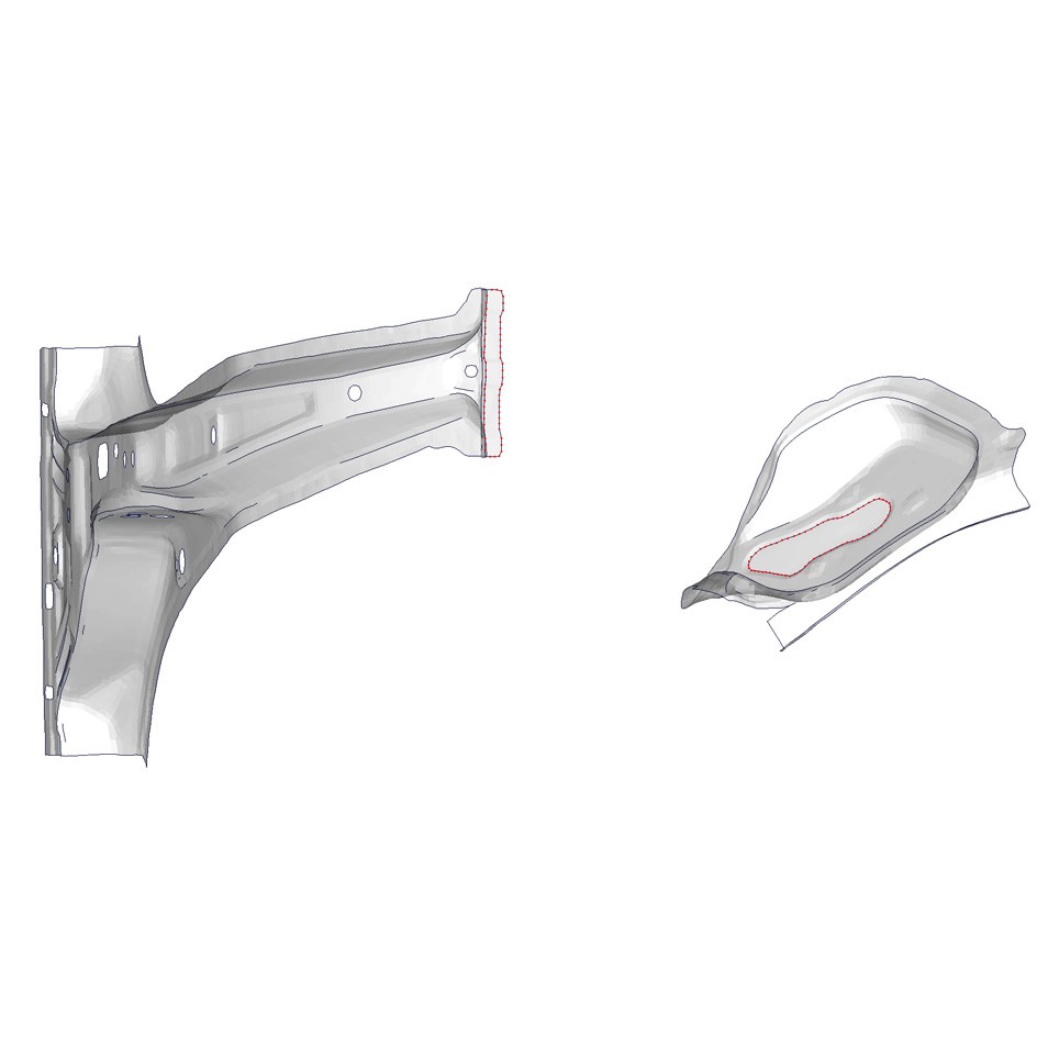
Changes in contours and holes
Changes such as cuts, extensions, additions, and deletions of contours can be detected. Similarly, changes in planar holes, such as closed, extended, newly formed, or shortened holes, can be detected.
ASCII comparison
Input files contain additional information not covered by the geometric comparison, for example, transformation blocks, comment blocks, etc. A smart ASCII difference analysis handles such input blocks. Currently, PAM-CRASH is supported; others, such as LS-DYNA, will be added.
* BETA CAE Systems is now part of Cadence